KiCad
KiCad1 is an open-source software tool for the creation of electronic schematic diagrams and PCB artwork. Although essentially treated as one program, KiCad is really more of a tight grouping of the following stand-alone software tools:
| Program name | Description | File extension |
|---|---|---|
| KiCad | Project manager | *.pro |
| Eeschema | Schematic and component editor | *.sch, *.lib, *.net |
| Pcbnew | Circuit board and footprint editor | *.kicad_pcb, *.kicad_mod |
| GerbView | Gerber and drill file viewer | *.g*, *.drl, etc. |
| Bitmap2Component | Convert bitmap images to components or footprints | *.lib, *.kicad_mod, *.kicad_wks |
| PCB Calculator | Calculator for components, track width, electrical spacing, color codes, and more… | None |
| Pl Editor | Page layout editor | *.kicad_wks |
The file extension list is not complete and only contains a subset of the files that KiCad supports. It is useful for the basic understanding of which files are used for each KiCad application. KiCad is mature open-source software, and is robust enough for typical use in lab as well as for more involved, complex electronic board designs.

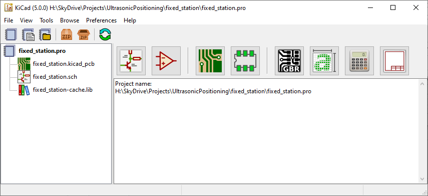
KiCad basic window. The icon row from left to right corresponds to Eeschema (schematic and component editors), Pcbnew ( board and footprint editors), GerbView, Bitmap2Component, PCB Calculator, and Pl Editor.
This tutorial is written using KiCad 5.0.0 on Windows 10. While significant changes are unlikely, be aware that small details may change if your install is different.
KiCad does not present any board-size limitation and it can easily handle up to 32 copper layers, up to 14 technical layers and up to 4 auxiliary layers. KiCad can create all the files necessary for building printed boards, Gerber files for photo-plotters, drilling files, component location files and a lot more. KiCad also incorporates ngspice, an open-source circuit simulator.
Being open source (GPL licensed), KiCad represents the ideal tool for projects oriented towards the creation of electronic hardware with an open-source flavor.
On the Internet, the homepage of KiCad is: http://www.kicad-pcb.org/
Downloading and installing KiCad
KiCad runs on GNU/Linux, Apple macOS and Windows. You can find the most up to date instructions and download links at:
http://www.kicad-pcb.org/download/
Under Apple macOS
Stable builds of KiCad for macOS can be found at: http://downloads.kicad-pcb.org/osx/stable/
Under Windows
Stable builds of KiCad for Windows can be found at: http://downloads.kicad-pcb.org/windows/stable/
Under GNU/Linux
KiCad Workflow
Despite its similarities with other PCB design software, KiCad is characterized by a unique workflow in which schematic components and footprints are separate. Only after creating a schematic are footprints assigned to the components.
Overview
The KiCad workflow is comprised of two main tasks: drawing the schematic and laying out the board. Both a schematic component library and a PCB footprint library are necessary for these two tasks. KiCad includes many components and footprints, and also has the tools to create new ones.
Initially, the process begins with schematic capture, as in any other tool. After the schematic has been defined, footprints are attached to each symbol on the schematic, and the information is then used to lay out the board.
The KiCad Tutorial has a detailed flowchart of the full board design process.
Some Notes on Fabrication
Both Oshpark (PCB only) and MacroFab(PCB + assembly) directly accept KiCad formats for fabrication. Naturally neither is the cheapest possible service, but for small projects the convenience can be an advantage.
Adapted in part from the KiCad Getting Started Tutorial, CC-BY-3.0 .
Pronounced ‘Key-CAD’. ↩︎