Circuits for COACH
 Analog Input Potentiometers
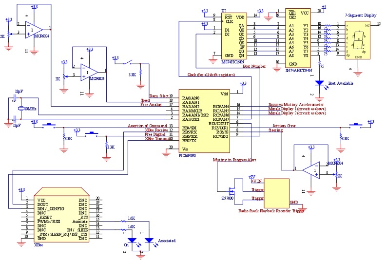
The 2k analog potentiometers (for speed and direction joysticks and the free analog input) are connected to a MCP6024 buffer to provide a linear analog voltage reading to the PIC.
Analog Input Potentiometers
The 2k analog potentiometers (for speed and direction joysticks and the free analog input) are connected to a MCP6024 buffer to provide a linear analog voltage reading to the PIC. Accelerometer for Suppress Mutiny Action
Only the Y axis of the accelerometer was used to detect side to side shaking motion.Vigorous shaking drives the analog signal coming out of the accelerometer to Ov and 3.3V.
Neutral voltage is 1.74V, and when the Y axis is tilted, min/max readings are 0.84V and 2.64V.
As a result, shaking to suppress mutiny is detected by setting an upper (2.75V) and lower (0.75V) bound in software which must be crossed for a duration of one second.
Digital Input Buttons
Each button is connected to 3.3V when closed, and uses a 3.3K pulldown resistor. Current required when switch is momentarily closed is: 3.3V/3.3K = 1mA.Mutiny Audio Output
To run, we raise a PORTC4 high, which is connected to the gate of a 2N7000.The 2N7000 triggers the playback recorder, which is operated off of 9V with an on board voltage regulator.
Boat Available LED
With a minimum forward voltage of 1.6V, powered by a 3.3V PIC, and a 75 Ohm current limiting resistor, the max current is 22.67mA. Max current output by the PIC on a single port is 25mA.7 segment displays
With a minimum forward voltage of 1.2V, powered by a 3.3V PIC, and a 75 Ohm current limiting resistor, the max current is 28.0mA. Max current output by the octal buffer SN74AHCT244N on a single port is 35mA.XBee
The XBee is connected to the master PIC using the asynchronous transmit and receive capability.COACH Runtime Calculation
P=IV.Assume pushing buttons and trigger for playback recorder trigger have a negligible impact on battery lifespan (1mA each for under 1s).
Team side select, when high, assuming it is 50% of the time, is 3.3V across 3.3K, which is 1mA, or at 50% time, 0.5mA.
Three 2k pots, driven at 3.3V, are constantly drawing 3.3V/2k = 1.65mA each, or 4.95mA total.
MP6024 buffer requires typically 1mA quiescent current, across 3.3V. One device has four buffers.
XBee requires 45mA to transmit. This occurs at 5Hz, and takes under 10ms.
XBee requires 50mA to receive. This occurs at 5Hz, and takes under 11ms.
MC74HC164N requires typically 8.0uA quiescent current, across 3.3V. There are three of these, so 24.0uA, or .024mA.
SN74AHCT244N buffer requires typically 80uA quiescent current, across 3.3V. There are three of these, so 240uA, or .240mA
The 7 sement display. The Team ID is typically a 6, which requires lighting 6 segments.
The MSB of the morale is typically 0, which is simply not lit. The LSB of the morale as an average of all number requires 4.9 segments.
Thus, assume a total of 11 segments are always lit.
With a min forward voltage of 1.2V, powered by 3.3V, and a 75 Ohm current limiting resistor, the max current per segment is 28.0mA.
For 11 segments, this is 308mA.
Assume that controller is often controlling a boat, so that boat available LED is on for 1/100 of the time, at 28.0mA.
PIC power use: 1.0 mA using external 10MHz oscillator at 3.5V.
Power: Team side select: P = 0.5mA * 3.3V = 1.65mW
Potentiometers: P = 4.95mA * 3.3V = 16.34mW
XBee transmit: P = 45mA * 3.3V * 10ms/1000ms = 1.49mW
XBee receive: P = 50mA * 3.3V * 11ms/1000ms = 1.82mW
MP6024 buffer: P = 1mA * 3.3V = 3.3mW
MC74HC164N shift register: P = .024mA * 3.3V = 0.08mW
SN74AHCT244N buffer: P = .240mA * 3.3V = 0.80mW
7 Segment Display: P = 308mA * 3.3V = 1016mW
Boat Available LED: P = 28mA * 3.3V * 1s/100s = 0.92mW
PIC: P = 1.0mA * 3.3V = 3.3mW
Total power draw: 1045.7 mW
10800 mWhours / 1045.7 mW = 10.33 hours runtime.