|
The Controller
|
|
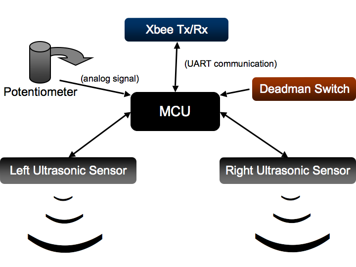
Inputs. A single microcontroller gathered a total of four inputs from the user across three sensing modalities:
Outputs.
|
|
|
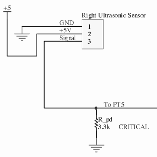
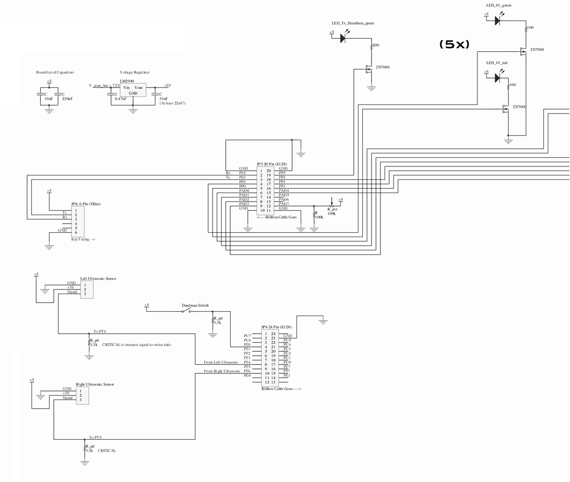
Distance Sensing. To sense the distance of each palm from the floor, we employed two ultrasonic sensors. Much of the interaction with this module is handled in software. Data is requested by pulling the signal line high for about five microseconds. The line is then converted to an input and captures the time between the ping of an acoustic pulse (logical high) and its echo (a second logical high). While there was little to wire, pull-down resistors were critical to reduce noise. |
|
|
Overall Controller Schematic. |
|
|
Current Check on the Voltage Regulators.
To ensure proper operation of our voltage regulators on the controller, it is ciritcal to ensure that the circuits they power will not demand
more current than the regulator can supply. We used a LM2940, a low-dropout 1A 5V voltage regulator the regulate the DC power
from the batteries in both the controller.
|
|
Controller Battery Lifetime Estimate.
The controller is powered by a 7.2V NiCad battery capable of storing 3000mA*hr of charge.
|
|
The Vehicle
|
|
System Overview. This section describes the system for our atoll capture vehicle (ACV), i.e., our boat. The design requirements for the ACV were to:
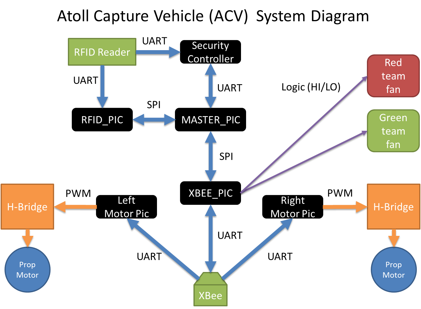
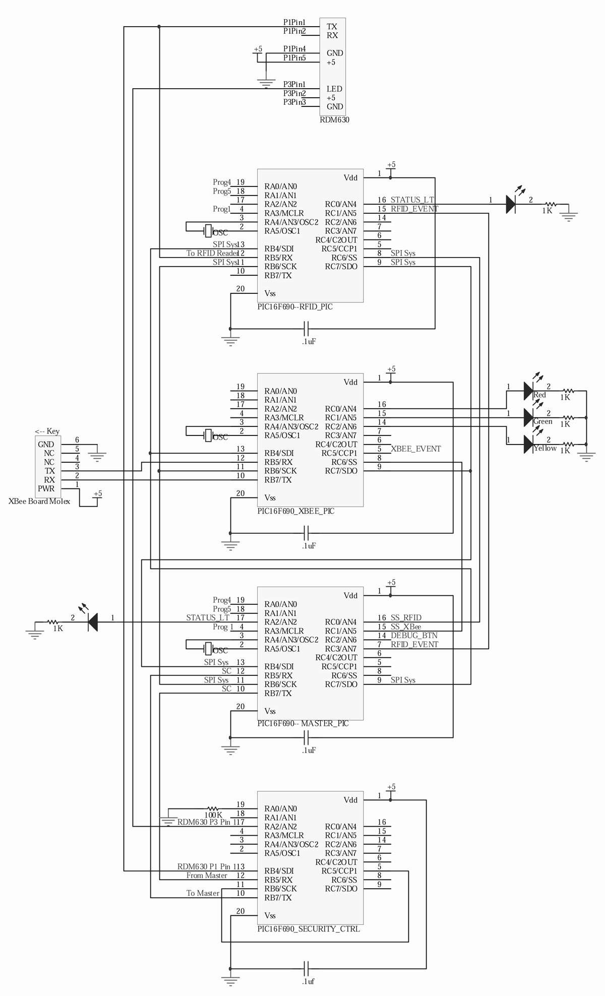
Referring to the system map below, we have six individual PIC16F690’s on our ACV, each performing unique tasks. The diagram shows what other devices each PIC talks to and which communication protocols they use. |
|
|
RFID Reader. The RFID reader receives RFID card serials using the RFID antenna, and sends them out on its transmit line via UART. RFID PIC. The RFID PIC receives the RFID serials, decodes them into HEX values, and transmits them to the MASTER PIC via SPI. The RFID PIC was coded in assembly as per a project requirement. RFID Reader. The RFID reader receives RFID card serials using the RFID antenna, and sends them out on its transmit line via UART. Master PIC. The master PIC is the master on the SPI system. All other chips on that network are slaves. The master PIC receives RFID serials from the RFID PIC and determines whether they belong to an atoll or a team color card. If the serials belong to an atoll, the master PIC sends them to the security controller via UART to retrieve the security keys necessary for capturing an atoll. The security controller was provided to us by the teaching team, and we communicate with it via a professor-determined protocol. Once the master PIC has the atoll serials and security keys or just the team color serials, it sends them to the XBee PIC via SPI using a team-determined protocol. XBee PIC. The XBee PIC receives and sends messages to the XBee wireless transceiver via UART, and it also receives messages from the master PIC via SPI. If the XBee PIC receives team color serials from the master PIC, initiates the class-determined communication sequence to find other boats on the same team. Once a teammate has been found, the XBee pic turns on one of the team color fans by raising a logic pin tied to a MOSFET. The fans blow around colored packing peanuts.If the XBee PIC receives atoll serials and security keys from the master PIC, it wirelessly broadcasts that information using a class-determined protocol to capture the atoll. Motor PICs. The motor PICs also receive messages from the XBee transceiver via UART. They are looking specifically for speed commands from the remote control. When they have received the appropriate message, they update the PWM signal that they are sending to the motor H-bridges. Each motor PIC runs the same code, but determines whether it controls the right or the left motor via an address line that is tied high or low. XBee. The XBee itself is an RF transceiver. The chip comes with the hardware layer and the low level sending and receiving software layers prebuilt. As a class, we designed a wireless communications protocol at the packet level to allow multiple teams to control their boats, capture atolls, and establish teammates without interfering with each other. |
|
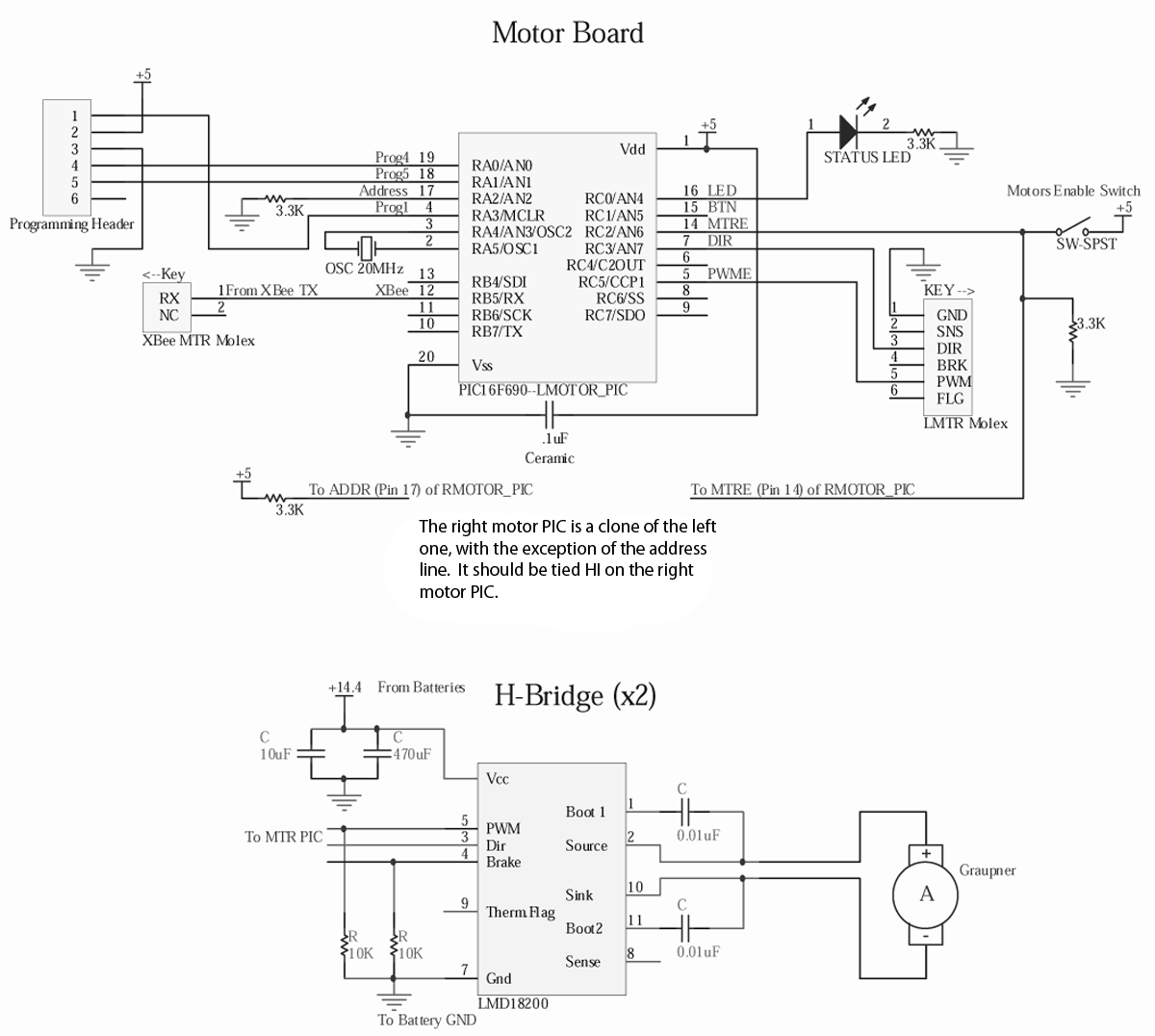
Propulsion. Below are the schematics for our motor PICs and H-bridges. See the system overview for a description of the functionality of the motor PICs. We used PIC16F690’s for the motor PICs. We used an LMD18200 H-bridge, which has 2A continuous and 3A peak current limits. It came in an SPDL lab kit with all the necessary capacitors and resistors. We chose our H-Bridge first and then chose our motors such that they would work within the operating limits of the H-bridge. |
|
|
|
|
Current Estimate on our Motor Driver Circuit. To ensure we do not burn out our H-Bridge, it was important to check the most current it will ever have to source is within spec. While no datasheet was available for the motors that drove our propellers, we measured the current at various loads. Under a typical load they drew about 1A and when stalled they drew about 2A. Our H-Bridge, an LMD18200, can deliver 3A so our factor of safety from toasting our H-bridge is: F.S. = 3A/2A = 1.5 |
|
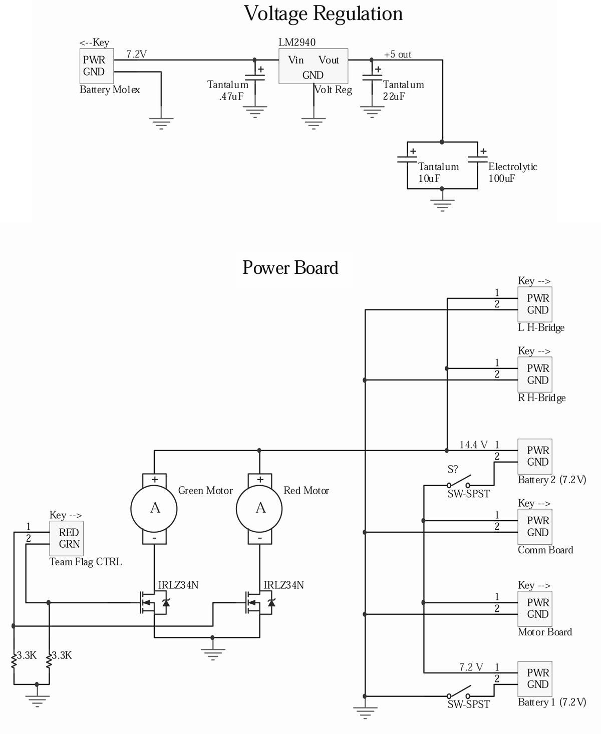
Power Management. Our power board acts as a switching station, taking power from two batteries and routing it to the circuits and the motors. We use battery 1 to supply 7.2 V to the motor and master boards. Then we use battery 1 and battery 2 in series to provide 14.2 V to the propeller motors and the team color fans. All of our logic circuits require 5V, but our batteries supply 7.2V each. Thus we use voltage regulators on each board to convert 7.2V to 5V. We chose the LM2940 because it has low dropout voltage (.5V typ) and high current capabilities (1A). Although 1A current is excessive for our application, we wanted to maintain the option of adding more LEDs later on in the project. We did not want to be limited by the 100 mA current limit of the LM2950. |
|
|
Communication. The master board contains four PIC16F690’s and an RDM630, which is an RFID reader. The devices work in tandem to scan RFID cards and pass the serial information to the radio. The devices are networked together via UART and SPI protocols. We used the standard hardware layers for each of these systems but designed our own software layers on top to handle our custom packets. |
|
|
|