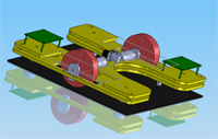
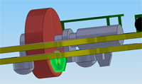
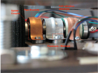
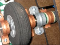
The lowermost level provides power transmission from the motors to the floor on the Death Star. The motors were mounted with a series of pipe-clamps that fit the outer housing of the motor and gear box. Washers and mechanical fasteners provide a vibration-free mount. A felt material compensates for the differences between the motor and gear-box housing, while dampening vibration. The wheels manually drilled and press-fitted to 3/16’’ shafts, and the shafts were attached to the gearbox via a spider coupler. The shaft was supported on either side by masonite puzzle pieces.
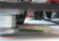
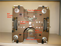
Tape Sensors, shown on the top right in bright green, are mounted directly on the lowest level. Five tape sensors are used in total – the center primarily for orientation, with either front two or back two for tape following, and all four front and back tape sensors used for goal orientation. (Placements pictured)


