Overview | Microcontroller | IR | Tape | Drivetrain | Power
The infrared sensor is used as the primary locator of flags and beacons. Each of the emittors sends an IR signal at 1.25KHz. The flags emit a signal at a 50% duty cycle and the beacons emit at either a 30% or 70% duty cycle, depending on the team side.
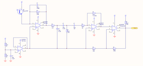
On the lower right of the schematic, a virtual ground is used, giving a clean 2.5V signal with low output current. This helps lower noise in the entire circuit.
The first stage of amplification is the transresistive stage, which converts the incoming infrared signal to a linear signal. The inverting capacitor helps reduce noise. A low pass is then used with a cut off frequency of 10KHz to once block out any unwanted signals. Next, a high pass filter with a cut off frequency of 1KHz blocks also blocks any unwanted signals. Together, they form a tight bandpass filter with a signal around 2.5V.
The 10KHz cutoff frequency is found by
1/(2*pi*150 Ohms*.1uF) = 10KHz
And the 1KHz cutoff frequency is found by
1/(2*pi*1.5KOhms*.1uF) = 1KHz
The next capacitor is put in place to help reduce any noise output from the filter stage.
The next stage is a gain stage, which is variable depending on the resistor chosen in negative feedback. The gain is found by:
G = -R2/R1 = -R2/1K
The last stage is a comparator with hysterisis stage. It looks for small changes around 2.5V, and sends a clean 0-5V signal to the microcontroller. The hysteris band is found by
V+= 2.5+
(5-2.5)*(10KOhms/(10KOhms+100KOhms+1.5KOhms))
=2.72V
V- = 2.5-2.5*(10KOhms/100KOhms)=2.25V
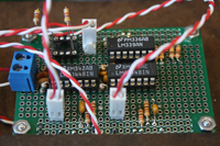
Below is the final circuit for the beacon sensor. The IR sensors look exactly the same.


