Overview | Microcontroller | IR | Tape | Drivetrain | Power
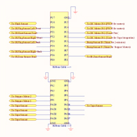
The E128 is the central processor, receiving inputs from a variety of sensors, and processing outputs in reaction to events. Below is an output and input schematic of the E128.
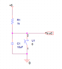
Several of the simple circuits (LED, Switches, etc), are directly placed on the microcontroller board. First, the bump sensor and the calibration push button all use the same debouncing circuit, as shown below.
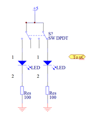
The team choosing switch uses a double pole double throw switch to drive two LEDs. The output of the switch is fed directly into the microcontroller. A 100 ohm resistor was chosen, as it gave the best light emission from the LED.
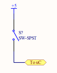
The state machine choosing switch uses a single pole single throw switch to feed a 5V signal to the microcontroller.
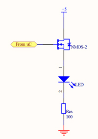
The calibration LED is used as a visual indicator to the operator on the status of calibration. As soon as tape sensor calibration is complete, the LED will shut off.
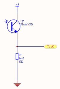
The flash sensor senses the initial flash from a camera. This flash ultimately tells the robot to begin the main software.
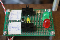
Below is an image of the final LED and switch circuit board.


