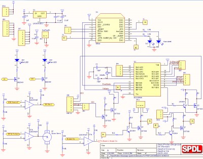
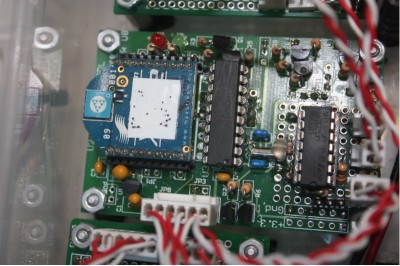
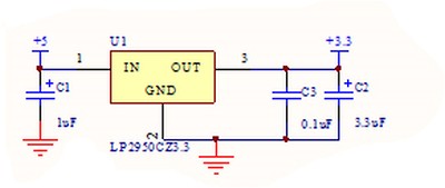
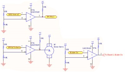
Since the Xbee operates at 3.3V, the incoming 5V power supply needed to be regulated down. The PIC is able to operate at 3.3V as well, so the power lines were shared. There were, however, multiple outputs of the PIC that needed to be level shifted back up to 5V for proper output to other components.
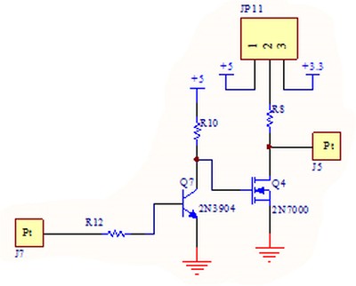
The two slave select lines to the other PICS were level shifted through the BJT/MOSFET pair. We found the cleanest rising edge came from using a 5K ohm base resistor and 1K ohm pull up resistors.
We found, however, that fast signals such as clocks and PWMs could not sufficiently be level shifted through the BJT/MOSFET pair. That is why a comparator was chosen to provide fast and crisp clock edges at 5V.
A reference voltage of 1.575V was chosen as it is a great halfway mark between 3.3V. A 10K resistor was chosen as a pullup due to its low power consumption. The quad comparator was used for the SCK, the PWM to the servo, and the toggle line to turn the kicker on.
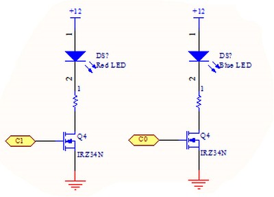
Two neon lights were used as team indicators to the user. The lights, normally used as a light accessory for a car, are rated for 12V and thus, needed to be powered by the 12V regulator. Since they are neon lights, and not regular LEDs, current consumption was determined using a 1ohm power resistor in series with the light. We found that each light was pulling 60mA of current and determined that was an acceptable amount.


