Circuits for Beacon Sensing
Description and Calculations
Flag Sensor
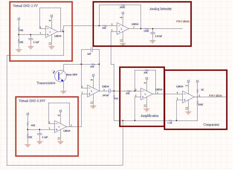
The aim of this circuit was to amplify the weak IR signals emitted by the flags on the playing field so that we could implement a flag following algorithm in our code. This circuit provides two outputs: a very clean comparator output for timing duty cycle (to ensure that we have locked onto a flag, and not a corner beacon), and an analog output for determining alignment with the beacon. The stages of the circuit are as follows:
Transresistive: the 26k resistor results in higher current output when the signal is further away. We intentionally rail the op-amp when the flag is close, so that the analog intensity measurement works at a range of a little over 3 feet, and because despite railing the op-amp our duty cycle only varies by 10%, which is still distinct from the corner beacons. The phototransistor is tied to ground, so using a 0.89V reference voltage allows for a maximum amplitude signal before the op-amp rails. A 1nf capacitor across the 26k resistor was instrumental in reducing noise.
Current out of transresistive circuit: 26k resistor, typ on 2mA.
Analog Intensity: an op-amp centered on 2.5V amplifies the signal from the transresistive stage by 20x, and passes it to a low pass filter to create a clean DC intensity level that is red by an AD port.
Gain Calc for amplification stage: 200k/10k = 20
Low pass corner frequency: R = 150k, C = .47uF, results in 2 Hz
Duty Cycle Timing: a high pass filter converts the transresistive output into distinct spikes, which are then amplified by 1.6x to boost the range to a little over 3 feet. In testing we achieved a range of over 18 feet using this circuit, but for playing the game we only wanted to detect flags in close proximity so as not to confuse the robot. This signal then goes to a comparator (note the tight hysteresis bands, indicating a clean, noise free signal).
High pass corner frequency: R = 670, C = .047uF, results in 5050 Hz
Gain Calc for amplification stage: 16k/10k = 1.6
Comparator Calcs: values 1k, 5.1k, 100k low = 2.38V, high = 2.62V
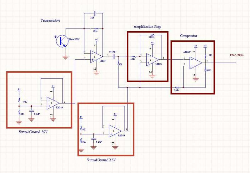
Corner Sensor
The aim of this circuit is to amplify and read the duty cycles of the corner beacons emitting at 1250Hz at either a 30% or a 70% duty cycle. Range is most important here: the robot should be able to see the corner beacons from anywhere on the field. Circuit layout is similar as the flag sensor circuit, minus the DC intensity measurement and with slightly different values. The transresistive circuit uses a 10k resistor, to avoid railing the op-amp even when in close proximity, and the amplification stage is 20x. The same hysteresis bands where used because we have the same clean signal.
Current out of transresistive circuit: 10k resistor, min on 1mA, typ on 2mA
High pass corner frequency: R = 670, C = .047uF, results in 5050 Hz
Gain Calc for amplification stage: 200k/10k = 20
Comparator Calcs: values 1k, 5.1k, 100k low = 2.38V, high = 2.62V
Schematics