Circuits for Encoders
Description and Calculations
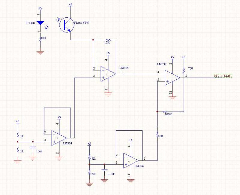
We attempted to use encoders on the drive motors to allow us very accurate absolute movement on the field, to compensate for uneven distribution of flags in our catcher, and to provide more power if pushing against another robot or having a corner stuck on a wall. The encoder circuit consisted of a transresistive stage to amplify the signal, which resulted in a clean signal with distinct rise and falls. As the output signal was centered around 1.25V, we used a comparator with slightly broader hysteresis bands centered at 1.25V to create a signal that then went to an input capture on the E128.
After we gave up on using encoders, we later reused the same circuit on the board we had made by replacing the tape sensor with an IR LED and a well shielded phototransistor. These were aimed at each other across the catcher entrance (a distance of about six inches). When there was a falling edge, indicating something broke the beam, we knew a flag had been captured.
Comparator hysteresis used: 100k, 10k, 750, low band = 0.98V, high band = 1.52V
Power requirement:
IR LED (LTE4208) Forward Voltage is max 1.6 Volts. Max continuous current is 50mA.
(5 - 1.2V) / 100 Ohms = 38mA.
With two IR LEDs driven through the encoder boards, it requires 78mA.
Schematics