Circuits for Motor Driving
Description and Calculations
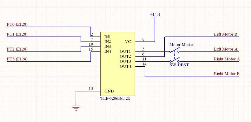
Drive-brake was used to actuate the Maxon drive motors, requiring two PWM lines for each motor. The circuit here is straight forward, as it is simply inputs and outputs to the TLE-5208 chip. We added a double pole single throw which allowed us to disconnect our motors, even when receiving a PWM drive signal through our program. This was a very useful feature for testing, as it allowed us to move the robot in neutral and it ensured the robot would not shoot off the table errantly when we turned on the master power.
One downside to this circuit is that we used the direct output from the nominal 14.4V batteries in series arrangement, and in our code we requested specific duty cycles. As the batteries drained during testing, the same requested duty cycle would drive our robot slower, or eventually, not at all. Originally, we planned to request duty cycles using the input from self built encoders, in which case this issue would not have arisen as a higher duty cycle could simply have been requested at lower battery to maintain speed.
To choose the motor drive frequency, there are three limitations: the motor characteristics itself, the H-Bridge response time, and what is acoustically tolerable. We chose to use a PWM frequency of 10000Hz, for the following reasons:
1) At lower PWM frequencies, which otherwise would have been desirable, the high pitched noise was intolerable.
2) H-Bridge response time significantly crops the requested duty cycle. However, due to acoustic requirements, we had little choice but to use a higher frequency.
3) Motor speed and torque, while significantly impacted because of the high duty cycle, were still sufficiently within our desired range that we rarely used more than a 40% duty cycle.
Stall Current: 3.510 Amps
Motor Coil Resistance: 1.8 ohms (very low!)
Timer prescale: divide by 4
Timer scale: divide by 2*6
PWM Period: 200
PWM frequency: 10 KHz
Schematics