Circuits for Tape Sensing
Description and Calculations
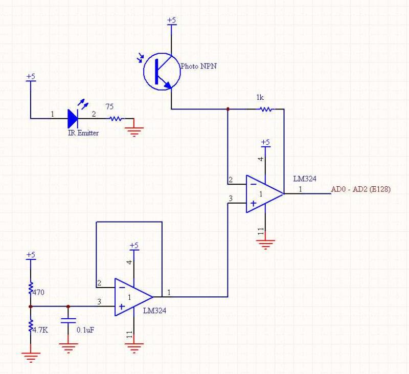
We used the tape sensors for the last stage of our state machine, when the robot needed to drive to the endzone and align itself so that all three beacons are in scoring position. They needed to detect sufficiently distinct levels for white, green, and black surfaces. A simple transresistive circuit was used to amplify the signal and output a DC signal, which was then read with AD ports.
IR LED (LTE4208) Forward Voltage is min 1.2 Volts. Max continuous current is 50mA.
(5V - 1.2 Volts) / 100 Ohms = 38 mA. With three tape sensors connected, it requires 114 mA.
Schematics