The other components on the display portion of the COACH included a team select switch, a “Not Paired” LED, and a “Mutiny in Progress” lamp.
The team select switch provided a hardware solution for using a single-pull single-throw switch to choose between two teams and report the selection back to the user. The circuit below turns on either the red or the green LED (but never neither nor both) when the switch is opened or closed (since this circuit had been built for a previous ME 218B project, and since green LEDs are significantly less expensive than blue LEDs, the green LED was used to represent membership on the blue team in this instance.) Thus the lighting of one of the LEDs is a direct result of the switch being toggled, and does not necessarily represent an acknowledgment in software of the team selection. However, an E128 input port is tied in to the circuit so that the software can be aware of the team selection, and there was never any problem with team selection in software mismatching that in hardware during this project.
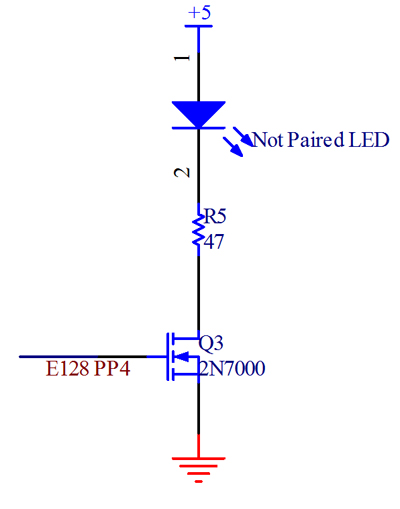
The “Not Paired” LED was to turn on whenever the “Not Paired” state was active in the software state machine, so it necessarily had to be under purely software control. Thus a simple N-channel MOSFET + current limiting resistor circuit was devised to turn the LED on at the appropriate intensity upon command from an E128 output pin. The MOSFET was needed because the E128 cannot source enough current directly to turn on an LED brightly.
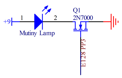
The mutiny lamp used the same circuit concept as the “Not Paired” LED; however, it required a higher voltage to shine visibly. The specification called for a 12 V power supply, but we found that 9 V was sufficient to see the lamp light up, so it was powered off of a 9 V battery (the internal resistance of the lamp was sufficient to limit the current from a 12 V supply, and thus also sufficiently limiting for a 9 V supply.


